Chapter 8
Attribute types
We describe in this chapter all the available types in TkZinc. They are listed by alphabetical
order.
NB: Two types are very important and their existence should be known by any new user of TkZinc: gradient and labelformat .
alignment
Specifies the horizontal alignment of an entity. The legal values are: left, right, center.
alpha
Specifies the transparency of an item. The value must be an integer from 0 (fully transparent) to 100 (fully opaque).
anchor
Specifies one of the nine characteristic points of a rectangle or a bounding box that will be used to position the object. These points include the four corners, the four edge centers, and the center of the rectangle. The possible values are: nw, n, ne, e, se, s, sw, w, center.
angle
Specifies an angle in degrees, the value must be an integer from 0 to 360 inclusive.
autoalignment
Specifies the horizontal alignments that should be used for track or way point fields depending on the label position relative to the position of the item. The attribute may have two forms: a single dash - means turning of the automatic alignment feature for the field; The other form consists in three letters which describe in order: the alignment to be used when the label is to the left of the item position, above or below the item position and to the right of the item position. The possible values for each letter is: l for left alignment, c for center alignment and r for right alignment. Here is an example: rll means right align the field if the label is on the left side of the item, and left align if the label is above, below or on the right of the item.
bitmap
This should be a string naming a valid Tk bitmap. The bitmap should be known to Tk prior to its use. TkZinc registers a set of bitmaps that can be used for any bitmap valued attribute (see section Bitmaps ). Extensions to Tk are available to create or manipulate bitmaps from a script. The value may also name a file containing a valid X11 bitmap description. The syntax in this case is @filename.
bitmaplist
This is an extension of the bitmap attribute type. It describes a list of bitmaps that will be the value of the attribute.
boolean
This is the description of a standard Tcl boolean value. The possible values are 0, false, no or off for the false value and 1, true, yes or on for the true value.
capstyle
This the description of a line cap. The possible values are butt, projecting and round.
dimension
This is a string that represent distance. The string consists in a floating point signed number.
edgelist
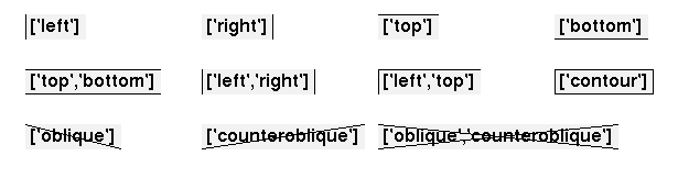
This is a list describing the edges of a border that should be considered for processing (e.g for drawing). The possible values are left, right, top, bottom, contour, oblique and counteroblique. The contour value is the same as the "left top right bottom" list. The oblique and counteroblique values describe diagonal segments from top-left to bottom-right and from top-right to bottom-left respectively. The following picture gives some edges examples.
fillrule
This is a string describing the rule used to compose the different contours or pathes of a curve. The allowed values are directly inspired from the openGL GLU tesselators as described for example in the chapter 11 of the “The OpenGL Programming Guide 3rd Edition The Official Guide to Learning OpenGL Version 1.2”, ISBN 0201604582. You can also refer to the example fillrule provided with TkZinc in zinc-demos . The allowed values are odd, nonzero, positive, negative, and abs_geq_2. The following figure shows the effect of fillrule value on curves with multiple contours:

font
This is a string describing a font. For an exhaustive description of what is legal as a font description, refer to the Tk font command man page. Just to mention to popular methods, it is possible to specify a font by it’s X11 font name or by a list whose elements are the font family, the font size and then zero or more styles including normal, bold, roman, italic, underline, overstrike.
Please note, that some font data are cached by TkZinc, on the application level. This is specially usefull with openGL. To avoid breaking the cache mecanism, you should avoid using a font once on only one item, then modifiy this item font and repeat this again and again.
gradient
This is a string describing a color gradient to be used for example to fill a surface. Gradient are also used to describe color of lines, even if in this case the lines are limited to one color with and optionnal alpha percentage.
The string may consist in a single color specification that will be used to paint a solid surface or a color with an alpha value or a list of gradient steps separated by | characters.
- The general pattern for an axial gradient is :
"=axial degre | gradient_step1 | ... | gradient_stepn" or
"=axial x1 y1 x2 y2 | gradient_step1 | ... | gradient_stepn"
The degre parameter defines the angle of the axe in the usual trigonometric sense. It defaults to 0. The x1 y1 x2 y2 parameters define both the angle and the extension of the axe.
- The general pattern for a radial gradient is :
"=radial x y | gradient_step1 | ... | gradient_stepn" or
"=radial x1 y1 x2 y2 | gradient_step1 | ... | gradient_stepn"
The x y parameters define the center of the radial. The x1 y1 x2 y2 parameters define both the center and the extension of the radial.
- The general pattern for a path gradient is :
"=path x y | gradient_step1 | ... | gradient_stepn"
The x y parameters define the center of the gradient.
- The general pattern for a conical gradient is :
"=conical degre | gradient_step1 | ... | gradient_stepn" or
"=conical degre x y | gradient_step1 | ... | gradient_stepn" or
"=conical x1 y1 x2 y2 | gradient_step1 | ... | gradient_stepn"
The degre parameter defines the angle of the cone in the usual trigonometric sense. The optional x y parameters define the center of the cone. By default, it is the center of the bounding-box. The x1 y1 x2 y2 parameters define the center and the angle of the cone.
All x and y coordinates are expressed in percentage of the bounding box, relatively to the center of the bounding box. So 0 0 means the center while -50 -50 means the lower left corner of the bounding box.
If none of the above gradient type specification is given, the gradient will be drawn as an axial gradient with a null angle.
Each gradient segment section has the general form:
color;alpha color_position mid_span_position
Each color can be specified as a valid X color : either a named color or #rrggbb value or any valid X color specification such as standard device-independent color specification (e.g. CIEuvY:<u>/<v>/<Y> as defined in the X man page). An alpha value can be applied to the color using the optional ;alpha parameter whose value should be in the 0..100 intervalle.
The color position tells where in the gradient surface, measured as a percentage of the total gradient distance, the color should start. The first gradient segment has its position set to 0 and the last segment has its position set to 100, regardless of the specification. The position can thus be safely omitted for these segments. The in between segments must have a position explicitly set. If not given, the position will default to 0.
The mid span position tells where in the current gradient segment should be the median color. The position is given in percentage of the current gradient segment distance. The mid span position can be used to obtain a non linear gradient segment, this is useful to describe relief shapes. This parameter can be omitted in which case it defaults to 50 and the gradient segment is perfectly linear.
A gradient segment can be specified as a single color. In this case a flat uniform fill will result.
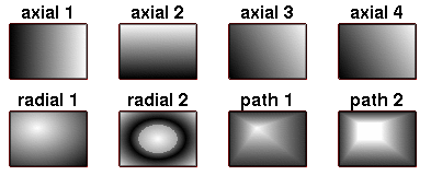
The following picture gives many examples of gradients. They correspond to the following values:
axial 1 : '=axial 0 | black|white' := 'black|white'
axial 2 : '=axial 90 | black|white'
axial 3 : '=axial 30 |black|white'
axial 4 : '=axial 30|black|black;0'
radial 1 : '=radial -14 -20|white|black'
radial 2 : '=radial 0 0 | white;50 0 70|black 50|white 100'
path 1 : '=path -14 -20|white|black;80'
path 2 : '=path -14 -20 |white|white 30|black;80'
gradientlist
This is an extension of the gradient attribute type. It describes a list of gradients that will be the value of the attribute.
image
This should be the name of a previously registered Tk image.
In pure Tcl-Tk only GIF, PPM and bitmap formats are available as source for images. With the Img extension many others popular formats are added including JPEG, XPM and PNG.
In Perl/Tk most image formats can be used, specially with Tk::JPEG or Tk::PNG modules.
Please note, that some image data are cached by TkZinc, on the application level. This is specially usefull with openGL. To avoid breaking the cache mecanism, you should avoid using an image once on only one item option, then modifiy this item option and repeat this again and again.
item
Describes an item id or a tag. If a tag is provided an item will be searched for the tag and the first matching in display list order will be used.
joinstyle
Describes a join style. The possible values are bevel, miter and round.
labelformat
The format is as follow. Parameters between [] are optional and take default values when omitted. Spaces can appear between blocks but not inside.
[WidthxHeight] [<field0Spec>] [<field1Spec>] ... [<fieldnSpec>]
Width and Height are strictly positive integers. They set the size of the clipping box surrounding the label. If not specified, there will be no clipping. If specified alone, they specify the size of the only displayed field which index is 0.
<fieldiSpec> ::= <fieldiSize>[<fieldiPos>]
Each fieldiSpec specify the size and position of the field numbered i.
<fieldiSize> ::= <sChar><fieldWidth><sChar><fieldHeight>
<sChar> ::= x|f|i|a|l
<sChar> specifies the meaning of the following <fieldWidth> or <fieldHeight>. Those are positive integers. Values for <sChar> have the following meaning :
- 'x' : the corresponding dimension (either width or height) is in pixel, according to the value of the <fieldWidth> or <fieldHeight>
- 'f' : the corresponding dimension is in percentage of the mean width/height of a character (in the field font). The following <fieldWidth> or <fieldHeight> gives the percentage. The value must be an integer between 0 and 100.
- 'i' : the corresponding dimension is in percentage of the size of the image in the field. The following <fieldWidth> or <fieldHeight> gives the percentage. The value must be an integer between 0 and 100. If the field contains no image, the dimension is 0.
- 'a' : the corresponding dimension is automatically adjusted to match the field’s content plus the given value in pixels.
- 'l' : the corresponding dimension is adjusted to match the global size of the label (not counting fields with 'l' size specs). The corresponding integer parameter is not used with this size specification. The global size of the label is considered when the labelformat is set. If some fields sizes change afterwards, you should set again the labelformat so that fields using a 'l' specification are re-computed. It is not possible to reference the field in another <fieldiPos> (see below).
<fieldiPos> ::= <pChar><fieldX><pChar><fieldY>.
<pChar> ::= +|<|>|^|$
<fieldX> and <fieldY> are either integer or index refering an other field of the labelformat.
Values for pChar have the following meaning :
- '+' : the position, either on the X or Y axis, is in pixel, possibly negative. XXX what does it mean if negative? The value is given by the corresponding <fieldX> or <fieldY>.
- '<' : The field will be at the left (or top) of the field refered by the corresponding index <fieldX> (or <fieldY>)
- '>' : The field will be at the right (or bottom) of the field refered by the corresponding index <fieldX> (or <fieldY>)
- '^' : The field will be left (or top) aligned with the field refered by the corresponding index <fieldX> (or <fieldY>).
- '$' : The field will be right (or bottom) aligned with the field refered by the corresponding index <fieldX> (or <fieldY>).
<fieldiPos> can be omitted if there is only one field.
leaderanchors
Describes where to attach the label leader on the label. Two positions can be defined: one when the label is at the right of current position and the other when the label is at the left of current position. Not to be confused with the regular rectangular anchors.
The format is: lChar leftLeaderAnchor [lChar rightLeaderAnchor]
If lChar is a |, leftLeaderAnchor and rightLeaderAnchor are the indices of the field that serve to anchor the label’s leader. More specifically the bottom right corner is used when leftLeaderAnchor is active and the bottom left corner is used when rightLeaderAnchor is active.
If lChar is %, leftLeaderAnchor and rightLeaderAnchor should be specified as widthPercentxheightPercent, each value being a percentage (between 1 and 100) of the width or height of the label bounding box. If rightLeaderAnchor is not specified it defaults to leftLeaderAnchor. If neither are specified, the center of the label is used as an anchor.
lineend
Describes the shape of the arrow at the beginning or end of a path. This is a list of three numbers describing the arrow shape in the following order: distance along the axis from neck to tip of the arrowhead, distance from trailing points to tip and distance from outside edge of the line to the trailing points (see canvas). If an empty list is given, there is no arrow.
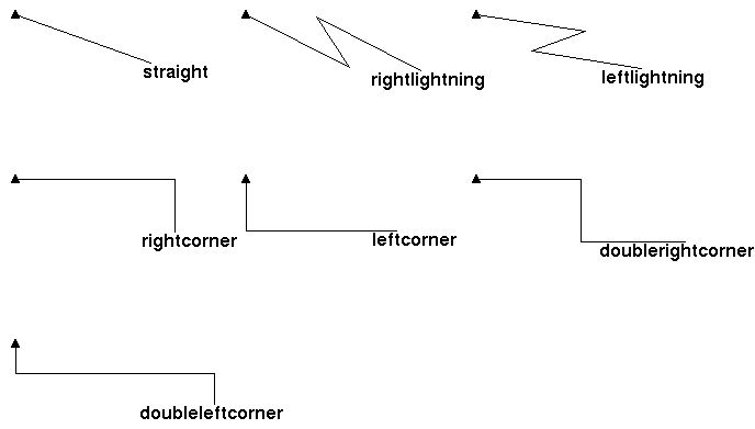
lineshape
Describes the shape of a path connecting two points. The possible values are straight, rightlightning, leftlightning, rightcorner, leftcorner, doublerightcorner and doubleleftcorner. The following figure shows these different line shapes:
linestyle
Describes the style of the dashes that should be used to draw a line. The possible values are simple, dashed, mixed and dotted.
mapinfo
This is the name of a previously registered mapinfo object (see the chapter The mapinfo related commands ) that will define the lines, arcs, symbols, and texts displayed in a map item.
point
This is a list of two floating point values that describes a point position or some two dimensional delta (used for example to describe the speed vector of a track item).
priority
A strictly positive integer value for the display priority.
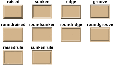
relief
Describes a border relief. The possible values, illustrated in the following figure are flat, raised, sunken, ridge, groove, roundraised, roundsunken, roundridge, roundgroove, raisedrule, sunkenrule.
string
Just what its name implies, a string.
taglist
This should be a list of strings describing the tags that are set for an item.
unsignedint
Describes an unsigned integer value.
window
A string describing an X window id. This id can be returned by the winfo id a-widget-path command.
[front]